Visual inertial odometry on a budget!!
Hello world! Today I want to talk about Visual inertial odometry and how to build a VIO setup on a very tight budget using ROVIO.
Brief intro
If you are new to Odometry or Visual Odometry I suggest to read some good papers or tutorials about this subject, but if you are too anxious to know more about it, here are the basics. Figure yourself driving your car and take a look at the odometer, you will read the number of miles or kilometers you have driven for but not where you have been or what turns did you take. Let’s say now that you can also read the steering angle of your wheels: if you keep track of both the steering angle and the odometer you will be able to reconstruct your trajectory assuming that it is planar! If we need to track the motion of a drone though, the whole procedure is a lot more complicated: a flying vehicle can move in 3 directions in space and can turn around 3 axis, so it has 6 degree of freedom. Keeping track of its full 6 D.o.F motion is complicated and requires some fairly complex and ingenious solutions: here comes in place Monocular Visual Odometry, the procedure of localizing a single camera with respect to 3d landmarks which are estimated online. In literature there are some extremely good examples of MVO as SVO, DSO, PTAM, ORB-SLAM, etc.. which are open-source and can be freely downloaded and compiled to play with.
VIO
Sometimes monocular vision alone is not sufficient for estimating quick movements because the quicker the vehicle is, the faster image features move in the captured frames. Since each frame is captured with a limited refresh rate (usually 30Hz or 60Hz), it is very likely that for abrupt and violent motions features are very difficult to track. Tracking loss cause inaccuracies and failures of standard vision-only monocular visual odometry. The basic idea is to fuse visual information with gyroscope and accelerometer outputs coming from an IMU. I will not talk in detail about the multiple solutions for designing IMU and camera fusion. I will just say that doing so, the imu drift is corrected in real time by camera “measurements” and visual odometry will benefit from the ability of an IMU to estimate quick and sudden motion, both rotational and linear.
An excellent example of a Visual Inertial Odometry algorithm is ROVIO. Take a look at this video from IROS2015
ROVIO
In order to run, ROVIO requires ROS to be installed in the system since all the input-output is managed through the ROS interface. Some additional dependencies are required but not much.
Each VIO system, in order to run properly, impose some strict requirements about the camera+IMU setup. Generally:
- global shutter camera -> rolling shutters cause bad artifacts while rotating or translating fast. Especially during fast rotations, straight lines tends to appear bent in the image. Normally every algorithm that does not take this into account just suffers from bad “measurements”.
- high rate IMU -> since an IMU is handled by integrating velocities and accelerations, an high refresh rate (>200Hz ideally) is required to reduce integration errors.
- synchronization -> ideally to each captured frame should correspond an IMU measurement captured at the same time. This requirement is fullfilled by hardware triggering, some good tutorials are available online.
What all of this means is that an high-performance VIO system is expensive. The question is: can I build a decently performing VIO setup without spending almost any money at all?
My Setup
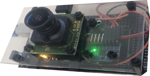
This is the camera+IMU setup I built. The camera is an old iDS uEye 1226, specs are highlighed below:
- model: uEye 1226
- resolution: 752x480
- shutter: global
- max fps: 87
- sensor model: MT9V032
- sensor size: 1/3”
As every commercial laptop (Dell Latitudes, Lenovo Thinkpads, etc..) is sold on ebay refurbished for very little money, also industrial cameras undergo to the same treatment. This is why you can find old Point Grey or Basler global shutter cameras for cheap. I payed around 50€ excluding shipping for the uEye. It came with an M12 lens mount (as the GoPro) and a long range 6mm lens designed for CCTV surveillance cameras. After swapping the lens with a 120° wide angle lens it was ready to run.
The IMU is a super cheap MPU6050 by InvenSense, it can be bought for around 5€ online. Usually it is found in many Arduino based applications because of its very low pricepoint but it can perform quite accurately in some circustances. Since it is equipped with a “Motion Processing Unit”, a tiny embedded processor to perform lightweigth computations, the Arduino itself can be spared some computational load, therefore being able to achieve a quite substantial refresh rate. While theoretically the refresh rate of the MPU6050 itself can go up to 1kHz while just pulling raw values, after filtering and publishing via USB to the pc, I can reach a stable rate of 160Hz. In my setup, camera and IMU are not synchronized.
The Arduino platform I am using is a chinese clone of the Arduino Mega (atmega 2560), it can be purchased from about 10€ on ebay.
Using ROS
ROVIO requires camera images and IMU measurements to be published in two topics by sending a standard image and Imu messages. In order to publish image messages it is needed to interface the camera with ROS: if the camera supports V4L then just a package as usb_cam can be used to pull frames and publish them in a given topic as sensor_msgs::Image. If not (as in my case) you will have to rely on custom packages usually available for common industrial camera manifacturers, for example MatrixVision, Basler or PointGrey and so on..
The camera must be first calibrated without the IMU using Kalibr, all the necessary instructions can be found in the wiki.
Interfacing with ROS the MPU6050 requires a little more effort but in many cases should work without actually playing with source codes. The procedure to publish a sensor_msgs::Imu from raw data requires some preliminary steps:
- install Jeff Rowberg’s I2Cdev library to handle the MPU6050
- install rosserial and build rosserial libraries in the arduino library folder. A great tutorial on that can be found here
- download and install the package tinyIMU_relay and the ros message type tinyIMU_msgs from this repo, rebuild rosserial libs to include tinyIMU messages in the Arduino SDK.
- in the Arduino flash the tinyIMU_arduino sketch from here.
The Arduino should now publish through the serial USB port a barebone message containing the least amount of data to carry gyroscope and acceleration information. This is done in order to achieve a reasonable publish rate, which is heavily bottlenecked from the read/write buffers of the Arduino. The full sensor_msgs::Imu is reconstructed and published by the package tinyIMU_relay. A full Imu message is composed of three fields:
- Orientation, quaterion parametrization
- Angular velocity
- Linear acceleration
Up to now only the last two fields are actually filled, the orientation is empty. That is because retrieving the orientation requires to integrate angular velocities (raw measurements from a gyro) and possibly filter them to reduce biases! Such computation is performed by the madgwick IMU filter.
An example ROS launchfile to start all the necessary nodes is analogue to the following:
<launch>

	<!-- ************************************ -->
	<!-- Bringup for camera + IMU + altimeter -->
	<!-- ************************************ -->

	<!-- Bringup camera -->
	<include file="$(find ueye_cam)/launch/mono8.launch" />

	<!-- Bringup IMU MPU6050 -->
	<node name="serial_node" pkg="rosserial_python" type="serial_node.py" >
		<param name="port" value="/dev/ttyACM0" />
		<param name="baud" value="57600" />
	</node>

	<node name="imu_raw2imu" pkg="tinyIMU_relay" type="tinyIMU_relay" >
		<param name="scale" value="true" />
	</node>

	<node name="imu_filter" pkg="imu_filter_madgwick" type="imu_filter_node" >
		<param name="use_mag" value="false" />
		<param name="stateless" value="false" />
	</node>
Some topic names to which each node subscribes and publishes are hard coded in the source, so it is necessary to take care of that!
Now that both the camera and the IMU are publishing information, the extrinsics (rototranslation) of the camera/IMU setup must be computed using Kalibr again. Camera intrinsics are initialized using the result from the vision-only calibration performed earlier (more details on the procedures in the wiki). Please note that ROVIO estimates online the camera/IMU relative position and orientation, the input extrinsics are treated just as an initial guess!
ROVIO
Now we can download and compile ROVIO if not already done and edit the configuration files to set the camera intrinsic parameters and the camera/IMU extrinsics. For a monocular setup + IMU, the yaml file should look like this one:
###### Camera Calibration File ######
image_width: 752
image_height: 480
camera_name: cam0
camera_matrix:
  rows: 3
  cols: 3
  data: [457.587, 0.0, 379.999, 0.0, 456.134, 255.238, 0.0, 0.0, 1.0]
distortion_model: plumb_bob
distortion_coefficients:
  rows: 1
  cols: 5
  data:  [-0.28368365,  0.07451284, -0.00010473, -3.55590700e-05, 0.0]
The extrinsics parameters should instead be written in the rovio.info file, also since the camera is just one it should be deleted the field:
Camera1{
	...
}
We can then create a custom launch-file like this one:
<launch>
  <node pkg="rovio" type="rovio_rosbag_loader" name="rovio" output="screen">
  <param name="filter_config" value="$(find rovio)/cfg/rovio.info"/>
  <param name="camera0_config" value="$(find rovio)/cfg/euroc_cam0.yaml"/>
  <param name="rosbag_filename" value="/home/riccardo/Desktop/desk.bag"/>
  <param name="imu_topic_name" value="/imu/data"/>
  <param name="cam0_topic_name" value="/camera/image_raw"/>
  </node>
</launch>
so that ROVIO will play the rosbag containing the topics /camera/image_raw and /imu/data (in my case) and estimate the camera trajectory!
VIDEOS
Here are two videos showing the behaviour of ROVIO with this el-cheapo visual inertial setup. The first video shows a desk scenario, very cornery and detailed. The second video shows a challenging little walking sequence where sudden illumination changes and reflections cause the algorithm to lose track of the environment therefore relying to the IMU (noisy) attitude and motion estimation.
I hope this post was interesting and helpful to clarify the steps to build a ROS-interfaced cheap setup. Now the videos, enjoy!